2022 October 8,
The first part of CS 311 develops, pretty much from scratch, a 3D graphics engine based on the triangle rasterization algorithm. Each day, we learn a new concept or algorithm in class, which you then implement in homework.
Except where otherwise noted, each homework assignment is due at the start of the next class meeting. Remember our late policy: If you don't have an assignment finished on time, then don't panic, but do e-mail me about it, so that we can formulate a plan for getting back on track.
All of your work today is individual. You read the syllabus, learn some C, write a small painting program as an exercise, and optionally install software on your own computer. You are welcome to do the installation first, so that you can do the other work on your own computer, but don't let installation problems prevent you from doing the other work.
Read the syllabus, by which I mean the front page of this course web site.
Using a CS department lab computer on the third floor of Olin, complete the following tutorials. Even if you already know C, you might want to skim them, to get a sense of what I expect students to know.
000mainHelloWorld.c: Study this file, which means: Download it, read it in a text editor, follow the instructions for compiling and running it, and figure out what each line of code does. If you want to test your understanding, then try altering a line, predicting what it will do, running the code, and checking your prediction.
010mainIntsDoubles.c: Study this file.
020mainIfWhileFor.c: Study.
030mainFunctions.c: Study.
Even if you already know C, you need to do this three-file tutorial, because it introduces the minimalist graphics library that we use for most of the course.
040pixel.h: Skim this file, which means: You should be familiar with what kind of stuff is in there, but you are not expected to read or understand the details.
040pixel.c: Compile this file into 040pixel.o by following the instructions at the top. You are not expected to read or even skim this file.
040mainLinking.c: Study this file.
Here is the work that you're going to hand in.
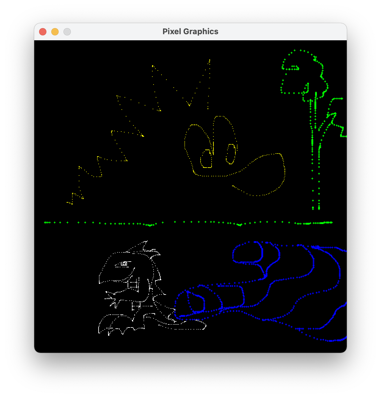
050mainPainting.c: Make a copy of 040mainLinking.c called "050mainPainting.c". Edit this file to make a simple painting program. Your program should make strokes of color whenever the user drags the mouse across the window. (Dragging means moving the mouse while holding down the left mouse button.) Your program should also let the user change the paint color by pressing the R, G, B, C, M, Y, K, and W (that's red, green, blue, cyan, magenta, yellow, black, and white) keys. To pass information among different parts of your user interface, you may have to use a few global variables. For example, here are some of mine, which I declare after the #include statements and before my first function definition:
double red = 1.0, green = 1.0, blue = 1.0;
int mouseIsDown = 0;
Just for fun, my program has a couple of extra features: letting the user change the brush size and clear the window. Here's a screenshot (click to enlarge):
Once your program is tested, make sure that your code is clean and commented. Follow these instructions to access the COURSES file server. Put your 050mainPainting.c file in your CS 311 hand-in folder on COURSES. Warning: Once you submit your file, you may no longer be able to edit it.
You are welcome to do all of CS 311 on the lab machines, but it might be more convenient for you to work on your own computer. In most cases, installing the necessary software is not difficult. Follow the installation instructions if you like.
If you have more time, then feel free to work individually on 070mainArrays.c, 080vectors.pdf, and 080vector.c from the next assignment.
All of your work today is individual. We start implementing our triangle-rasterizing graphics engine. So your first programming task is to make the rasterizer. It is important that you carefully write and thoroughly test this code, because the next four weeks of the course depend on it.
060triangle.c: Make this file. In it write the following function to rasterize a triangle. The inputs are three vertices of a triangle and an RGB color. Assume that the vertices are not co-linear. Assume that they are given in counter-clockwise order. Make no other assumptions. For each pixel in the triangle, the function calls pixSetRGB with the given RGB color. Write helper functions if you wish. My implementation uses a helper function triRenderWithALeft.
void triRender(
        double a0, double a1, double b0, double b1, double c0, double c1,
        double r, double g, double b) {

}
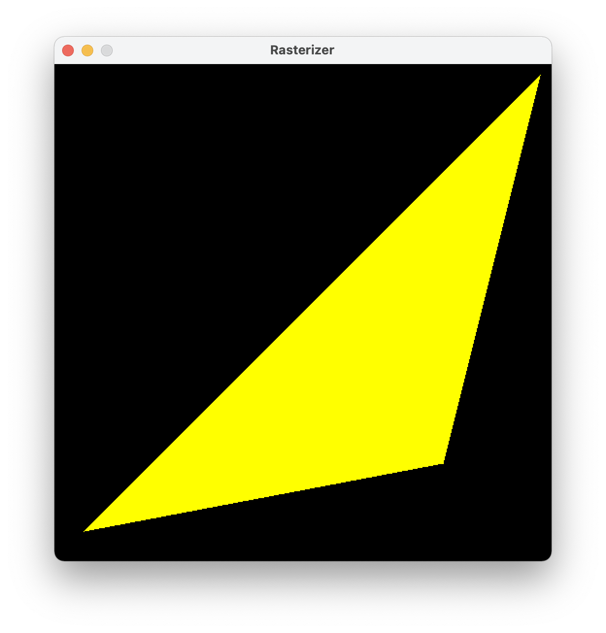
060mainRasterizing.c: Make this file, perhaps by copying 040mainLinking.c. Near the top, but after all header files, #include 060triangle.c to include your rasterizer code. In the main function, demonstrate that your rasterizer works. Here's a screenshot of mine:
Make sure that 060triangle.c and 060mainRasterizing.c are functioning, clean, and commented. Put them in your CS 311 hand-in folder on COURSES.
This chunk of work is not handed in today. We use it on Day 03 and hand it in then. But do it now.
070mainArrays.c: Study.
080vectors.pdf: Study.
080vector.c: Some of these vector functions are already written. Implement the others. (We add to this file in the coming weeks.)
If you have more time, then feel free to work individually on the next chunk of work: 080triangle.c or 090matrices2By2.pdf, 090mainMatrices2By2.c, etc.
All of your work today is individual. We add the ability to interpolate quantities across triangles. After rasterization, interpolation is the second-most fundamental concept in our graphics engine. It enables a wide variety of effects — far beyond what we see today.
080triangle.c: Make a copy of your 060triangle.c. In it, alter your rasterizer to use C arrays wherever appropriate. For starters, the interface of the triRender function should be changed as follows. In the implementation, a0 becomes a[0], etc.
void triRender(
        const double a[2], const double b[2], const double c[2],
        const double rgb[3])
080mainRasterizing.c: In a copy of 060mainRasterizing.c, include 080vector.c and then 080triangle.c rather than 060triangle.c. Update your demonstration code to make sure that the new triRender works, before proceeding to the next steps.
090matrices2By2.pdf: Study.
090mainMatrices2By2.c: Study.
100matrix.c: This file specifies the interfaces for various matrix functions. Fill in the implementations. (We add to this file in the coming weeks.)
100mainTesting.c: Without editing this program at all, you should be able to compile and run it. It should show a large yellow triangle slowly rotating, dimming, and brightening. If you encounter any errors, then something is wrong in your 080vector.c, 100matrix.c, or 080triangle.c.
110triangle.c: In a copy of 080triangle.c, change the interface for triRender to
void triRender(
        const double a[2], const double b[2], const double c[2],
        const double rgb[3], const double alpha[3], const double beta[3],
        const double gamma[3])
The three new parameters are RGB colors at the vertices. Implement linear interpolation of color. Modulate the interpolated color with the other color rgb. Use functions from 080vector.c and 100matrix.c wherever they are appropriate. For example, at each rasterized pixel I use vecSubtract, mat221Multiply, vecScale, vecAdd, and vecModulate. (But don't include those files here. They are included in 110mainInterpolating.c.)
110mainInterpolating.c: In a copy of 100mainTesting.c, include 110triangle.c, and demonstrate that your color interpolation works. Here's a screenshot of mine, which uses red, green, and blue vertices and a yellow rgb:

You have six files to hand in: 080vector.c, 080triangle.c, 080mainRasterizing.c, 100matrix.c, 110triangle.c, 110mainInterpolating.c. As usual, check that your files are functioning, clean, and commented. Then submit them to COURSES.
If you have more time, then feel free to get started on the first chunk of the next assignment.
Today you start to work with your assigned partner (if any). When you need to use old files, you can use whichever partner's old files you prefer. We implement texture mapping, which is arguably the most important graphical effect enabled by interpolation.
120mainPointers.c: Study.
130mainStructs.c: Study.
stb_image.h: Download. You are not expected to read or even skim this file. Parts of it are hard to understand unless you know C well. This is a public-domain image-loading library. Despite the ".h" suffix, it contains not just interfaces but also implementations. This library is used by a certain function in 140texture.c, which I have already written for you.
140texture.c: Skim this file, which means: You should be familiar with all of the constants, structs, and functions, but you may not understand the details of some of the function implementations. This file defines a data type, texTexture, that we use for texture mapping. It's all complete, except that the texSample function has a cosmetic bug: When asked for linear filtering, it responds with nearest-neighbor filtering. You fix that bug later in this assignment. For now, just pretend that there is no bug.
140triangle.c: In a copy of 110triangle.c, update triRender to have the following interface. The fifth argument is a pointer to a texture that has been initialized elsewhere. The quantities being interpolated are now texture coordinates, not colors. Just before you call pixSetRGB, perform a texture lookup using texSample. Modulate that texture RGB by rgb, and pass that modulated color to pixSetRGB.
void triRender(
        const double a[2], const double b[2], const double c[2],
        const double rgb[3], const texTexture *tex, const double alpha[2],
        const double beta[2], const double gamma[2])
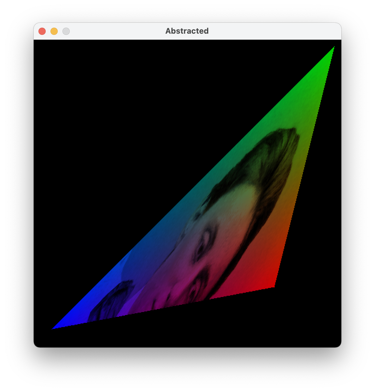
140mainTexturing.c: In a copy of 110mainInterpolating.c, include 140texture.c and 140triangle.c. Demonstrate your new triRender. Somewhere after pixInitialize you'll have to make a texTexture to pass to triRender. Use texInitializeFile, and don't forget to texFinalize before you pixFinalize. (Resources should be dismantled in last-in-first-out order.) The vertices should have texture coordinates ST instead of color RGB. Feel free to deactivate the rotation, dimming, and brightening. Depending on the image that you use, the texel dimension might be 1, 3, 4, or some other value. Whatever it is, use the texture in whatever (non-trivial) way you want. If your results look wrong, and you don't know why, then try a different image; the STB library doesn't handle some images well. Here's a screenshot of my program, which uses a colorized photograph of one of my favorite mathematicians:

150texture.c: In a copy of 140texture.c, find the part of texSample where linear filtering is supposed to happen, and replace it with your own linear filtering code. Multiple calls to texGetTexel are required. Do not assume that the texels are RGB colors. Instead assume that they are arrays of dimension tex->texelDim. It's manageable if you use vecScale, vecAdd, etc.
150mainTexturing.c: In a copy of 140mainTexturing.c, include 150texutre.c. Add a global variable and a keyboard handler, so that by pressing GLFW_KEY_ENTER the user can quickly switch between nearest-neighbor and linear filtering. It will help you evaluate your filtering. If you cannot see much of a difference, then try using a coarser image — maybe just eight pixels wide and eight pixels tall?
You have four files to hand in: 140triangle.c, 140mainTexturing.c, 150texture.c, 150mainTexturing.c. Make sure that they are functional, clean, and commented. Make sure that both partners are credited in a comment at the top of each file. Make sure that both partners have a copy of each file. Then, just one partner submits the files to COURSES. Please also submit the image file that you used, in case that helps us debug.
Today you continue working with your partner. We introduce the fragment shader. This abstraction makes our graphics engine more flexible and better aligned with how graphics is done in the real world. You also get a chance to design your own creative effect.
160mainAbstracted.c: Study this file, but you won't be able to run it yet, for several reasons. First, you haven't written the shadeFragment function yet. Second, you don't have 170triangle.c. Third, you don't have 170shading.c. Fourth, your texture image file might not have the same name as mine. In the following instructions, we fix these issues in reverse order.
170mainAbstracted.c: In a copy of 160mainAbstracted, change the texture image file name.
170shading.c: Create this file. In it, define a struct data type, following 130mainStructs.c, called shaShading. Right now it just has three int members: unifDim, attrDim, and texNum, in that order. (Later in the course it holds more information.)
170triangle.c: Make a copy of 140triangle.c. In it, update the interface for triRender to the one below. You now have an array of uniform information, an array of texture pointers, three arrays of vertex attributes, and a shaShading struct that specifies how many elements are in each of those arrays. Edit your implementation so that, at each rasterized pixel, it computes an interpolated attribute array attr of dimension sha->attrDim, invokes shadeFragment to get an RGB color, and passes this color to pixSetRGB. (Let me emphasize that pixSetRGB is called from triRender, not from shadeFragment. Also, keep in mind that sha->attrDim might be any integer greater than or equal to 2. Your code should work whether sha->attrDim is 2, 25, or 100, for example.)
/* Assumes that the 0th and 1th elements of a, b, c are the 'x' and 'y'
coordinates of the vertices, respectively (used in rasterization, and to
interpolate the other elements of a, b, c). */
void triRender(
        const shaShading *sha, const double unif[], const texTexture *tex[],
        const double a[], const double b[], const double c[])
170mainAbstracted.c: Now write shadeFragment. It should modulate a sampled color, interpolated color, and uniform color all together. Run your program. Here's mine:
180mainEffect.c: Make a copy of 170mainAbstracted.c. Edit it to produce an entirely different visual effect. Be creative! My only requirement is that you must use at least two textures. The most interesting edits are in shadeFragment, but there may be some supporting edits throughout 180mainEffect.c. The rest of your files, such as 170triangle.c, should be unchanged. If you want me to share your demo with the class, then e-mail me a screenshot and a brief (one or two sentences) explanation of how you made your effect. For example, mine is below. I use the vertex attribute texture coordinates to sample an RGB from a cloud texture, then use the RG from that RGB as texture coordinates to sample the final RGB from my usual Emmy Noether texture.

Make sure that 170shading.c, 170triangle.c, 170mainAbstracted.c, and 180mainEffect.c are functioning, clean, and commented. Make sure that both partners are credited at the top of each file. Share the files with your partner. Submit one copy of each file to COURSES. Also submit your texture files.
As you continue working with your partner, we start to draw meshes made of many 2D triangles. Also we introduce the vertex shader abstraction.
190mesh.c: Skim. This file implements a data type for triangular meshes. You can see initializer/finalizer functions, accessor functions, and functions to read and write files. There's also meshRender. Fill in its implementation, using other functions such as meshGetTrianglePointer, meshGetVertexPointer, and triRender. Don't overlook the part of the specification about attrDim.
190mesh2D.c: Skim. This file offers "convenience" functions for building some common kinds of 2D meshes.
190mainMesh.c: Make this file, perhaps starting from a copy of 170mainAbstracted.c. Demonstrate that your mesh renderer is working correctly. I recommend using the convenience builders and one texture. Don't forget to finalize everything that you successfully initialize.
Now we make a big change to our graphics engine. It requires alterations to several files (because our engine is not very well abstracted, because we're learning how to abstract it right now). The change is: What we used to call attributes are now either attributes or varyings, depending on whether they exist before or after the vertex shader.
200shading.c: In a copy of 170shading.c, add an int varyDim member to the end of the shading struct.
200triangle.c: Make a copy of 170triangle.c. Your triangle code will never again see an attribute vector. It will see varying vectors instead. So make all required changes. For example, replace sha->attrDim with sha->varyDim. When I did this, my code had a bunch of variable names and comments that referred to attributes, so I took this opportunity to clean those up too.
200mainAbstracted.c: Make a copy of 190mainMesh.c. Because shadeFragment is called only by triRender, and triRender sees varyings not attributes, it follows that shadeFragment sees varyings not attributes. So, in shadeFragment, replace attr with vary, ATTRX with VARYX, etc. Just below shadeFragment, add the shadeVertex function below. Above shadeFragment, keep the constants ATTRX, etc., but add constants VARYX, etc. And don't forget to initialize the varyDim member of your shading struct in main.
/* Outputs vary, based on the other parameters, which are unaltered. Like
shadeFragment, this function should not access any variables other than its
parameters and any local variables that it declares. */
void shadeVertex(
        int unifDim, const double unif[], int attrDim, const double attr[],
        int varyDim, double vary[]) {
    /* For now, just copy attr to vary. Baby steps. :) */
    vary[VARYX] = attr[ATTRX];
    vary[VARYY] = attr[ATTRY];
    vary[VARYS] = attr[ATTRS];
    vary[VARYT] = attr[ATTRT];
}
200mesh.c: In a copy of 190mesh.c, in meshRender, use shadeVertex to transform attributes to varyings before passing them to triRender. (I can imagine two ways to do this. One way saves time by spending memory, and the other way saves memory by spending time. I recommend that you pursue the second way, because it is simpler. If you don't know what I'm talking about, then do whatever makes sense to you, but try to figure out what I mean later.)
200mainAbstracted.c: Test whether everything works up to this point. Then add one uniform to express rotation and two uniforms to express translation. Implement the rotation followed by translation in shadeVertex. I recommend that you have a time step handler that animates the rotation and/or translation, because animations give you more debugging information than still images do. Here's a still image of my program:

As always, make sure that your files — 190mesh.c, 190mainMesh.c, 200shading.c, 200triangle.c, 200mesh.c, and 200mainAbstracted.c — are functioning, clean, commented, and credited. Make sure both partners have a copy, and submit one copy to COURSES.
If you have more time, then feel free to get started on Day 07's work.
News: This work is due at the start of Day 09 (Friday), not the start of Day 08 (Wednesday).
Today's work with your partner doesn't really add any new features. Instead, it organizes, accelerates, and stress-tests the code that we already have. That's valuable work, because we're about to build a 3D graphics engine atop this 2D foundation, and we want the foundation to be as strong as possible.
Together, the vertex and fragment shaders constitute a single shader program. A shaShading struct should describe a complete shader program, including the functions. For then we can conveniently switch shader programs at run time. (A real graphics program might use several shader programs in each animation frame.)
210mainFunctionPointers.c: Study.
220shading.c: In a copy of 200shading.c, add shadeVertex and shadeFragment members to the end of the shading struct. They are function pointers.
220triangle.c: In a copy of 200triangle.c, replace shadeFragment with sha->shadeFragment. Easy. :)
220mesh.c: In a copy of 200mesh.c, replace shadeVertex with sha->shadeVertex.
220mainAbstracted.c: Study this file, focusing on the two comments that describe new stuff. Change the name of the texture image file but nothing else in this C file. Test that it works with the rest of your code. If not, then fix the rest of your code, not this file.
The next issue is that our approach to writing shadeVertex is inefficient (why?), and it will become more inefficient as the course progresses. So let's take this opportunity to restructure the code a bit.
230matrices3By3.pdf: Study.
230matrix.c: In a copy of 100matrix.c, implement the following functions.
/* Multiplies the 3x3 matrix m by the 3x3 matrix n. The output CANNOT safely
alias the input. */
void mat333Multiply(
        const double m[3][3], const double n[3][3], double mTimesN[3][3])

/* Multiplies the 3x3 matrix m by the 3x1 matrix v. The output CANNOT safely
alias the input. */
void mat331Multiply(
        const double m[3][3], const double v[3], double mTimesV[3])

/* Builds a 3x3 matrix representing 2D rotation and translation in homogeneous
coordinates. More precisely, the transformation first rotates through the angle
theta (in radians, counterclockwise), and then translates by the vector t. */
void mat33Isometry(double theta, const double t[2], double isom[3][3])
230mainHomogeneous.c: Make a copy of 220mainAbstracted.c. Replace the three rotation-translation uniforms with nine uniforms. They store a 3x3 matrix. In your time step handler, configure this matrix using code like the code below. The rotation angle and translation vector are global variables, one or both of which is altered by the time step handler. UNIFMODELING is a compile-time constant storing the index of the first (0th) entry of the matrix in the uniforms. You are not expected to fully understand the pointer manipulation in the third line of code. Intuitively, it packs a 3x3 matrix into a 9-dimensional vector.
double isom[3][3];
mat33Isometry(rotationAngle, translationVector, isom);
vecCopy(9, (double *)isom, &unif[UNIFMODELING]);
230mainHomogeneous.c: In shadeVertex, you can "unpack" the 9-dimensional vector back into a 3x3 matrix and use it as follows. You have to figure out what attrHomog and varyHomog are, and how they fit into the rest of your code. Once you're done, test your program. Its output should be identical to that of 220mainAbstracted.c.
mat331Multiply((double(*)[3])(&unif[UNIFMODELING]), attrHomog, varyHomog);
Let's make a serious test of everything up to this point, so that we can be confident in our upcoming 3D work.
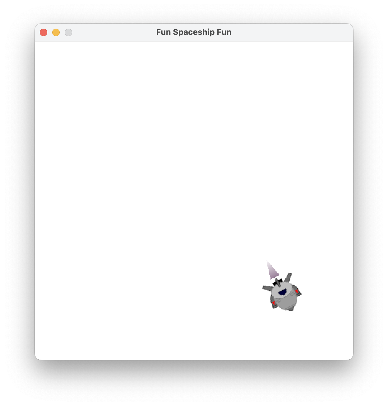
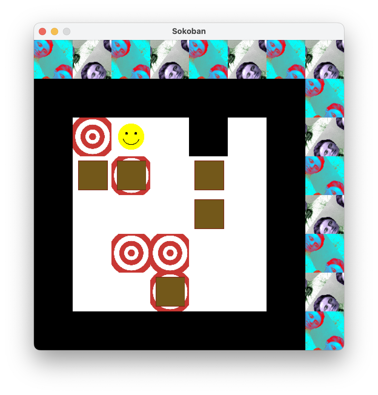
240mainShadings.c: Make a demo program that renders (at least) two meshes with (at least) two different shading structs. To make the shading structs genuinely different, let's say that they should have different shader functions attached. They may also differ in their integer members. If you want me to share your demo with the class, then e-mail me a screenshot and a short description. Screenshots of two examples are below. In the first example, the body of the spaceship is a square texture-mapped with one texture. When the user is pressing a certain key, the spaceship accelerates forward, and an exhaust plume appears. The exhaust plume is a triangle with no texture. The second example is a Sokoban clone with a psychedelic animated background. (These are prototypes of video games. Your program does not have to be interactive at all.)
Clean up and hand in 220shading.c, 220triangle.c, 220mesh.c, 230matrix.c, 230mainHomogeneous.c, and 240mainShadings.c. Please include any texture files that are needed to run your software.
If you have more time, then feel free to get started on the next chunk of work.
No new work is assigned today. Your work from Day 07 is due at the start of class on Day 09.
Today we transition from 2D to 3D. This change requires some math, which you and your partner will implement. It requires 3D meshes, which I have implemented for you. It requires numerous other small changes, as we discuss in class.
250vectorsMore.pdf: Study.
250vector.c: In a copy of 080vector.c, implement the following functions.
/* Returns the dot product of the vectors v and w. */
double vecDot(int dim, const double v[], const double w[])

/* Returns the length of the vector v. */
double vecLength(int dim, const double v[])

/* Returns the length of the vector v. If the length is non-zero, then also
places a normalized (length-1) version of v into unit. The output can safely
alias the input. */
double vecUnit(int dim, const double v[], double unit[])

/* Computes the cross product of v and w, and places it into vCrossW. The
output CANNOT safely alias the input. */
void vec3Cross(const double v[3], const double w[3], double vCrossW[3])

/* Computes the vector v from its spherical coordinates. rho >= 0.0 is the
radius. 0 <= phi <= pi is the co-latitude. -pi <= theta <= pi is the longitude
or azimuth. */
void vec3Spherical(double rho, double phi, double theta, double v[3])
250matrices4By4.pdf: Study.
250matrix.c: In a copy of 230matrix.c, implement the following functions. You might find it useful to implement helper functions such as mat33Add. That's up to you. I've already implemented mat44Transpose for you.
/* Given a length-1 3D vector axis and an angle theta (in radians), builds the
rotation matrix for the rotation about that axis through that angle. */
void mat33AngleAxisRotation(
        double theta, const double axis[3], double rot[3][3])

/* Given two length-1 3D vectors u, v that are perpendicular to each other.
Given two length-1 3D vectors a, b that are perpendicular to each other. Builds
the rotation matrix that rotates u to a and v to b. */
void mat33BasisRotation(
        const double u[3], const double v[3], const double a[3],
        const double b[3], double rot[3][3])

/* Computes the transpose M^T of the given matrix M. The output CANNOT safely
alias the input. */
void mat44Transpose(const double m[4][4], double mT[4][4]) {
    for (int i = 0; i < 4; i += 1)
        for (int j = 0; j < 4; j += 1)
            mT[i][j] = m[j][i];
}

/* Multiplies m by n, placing the answer in mTimesN. The output CANNOT safely
alias the input. */
void mat444Multiply(
        const double m[4][4], const double n[4][4], double mTimesN[4][4])

/* Multiplies m by v, placing the answer in mTimesV. The output CANNOT safely
alias the input. */
void mat441Multiply(
        const double m[4][4], const double v[4], double mTimesV[4])

/* Given a rotation and a translation, forms the 4x4 homogeneous matrix
representing the rotation followed in time by the translation. */
void mat44Isometry(
        const double rot[3][3], const double trans[3], double isom[4][4])
250mesh3D.c: Skim. This file contains "convenience" functions for building 3D meshes. The attribute dimensions are 3 + 2 + 3 = 8. The first three attributes are X, Y, Z position. The next two attributes are S, T texture coordinates. The last three attributes are called N, O, P. We talk about them later in the course.
250triangle.c: Now that we're working in 3D, it is possible that triRender will be passed a co-linear or clockwise-ordered triangle. In those cases, triRender's behavior used to be unspecified. Now we specify that it should draw nothing. My code has always (since 110triangle.c) done this backface culling automatically, by checking that the determinant returned by mat22Invert is positive. If you've been doing the same, then 250triangle.c is just a copy of 220triangle.c. If you've not been doing the same, then you need to implement this feature now. The details depend on how your triRender code is structured. If, like me, you always keep the vertices counter-clockwise, then do the determinant test at the start and be done. But other students reorder the vertices into clockwise order before rasterizing. They might consider a cross product test before reordering, instead of my determinant test after reordering. If you don't know what I'm talking about, then re-read 250vectorsMore.pdf.
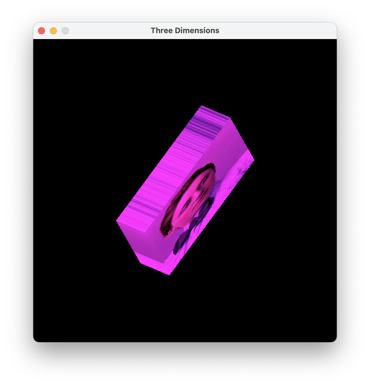
250main3D.c: Alter the name of the texture image file, but make no other alterations. Study. The program should display a rotating 3D box as in the screenshot below. If not, fix your other files. (I made this file by starting from 230mainHomogeneous.c and making many small edits as described in class.)
Clean up and hand in 250vector.c, 250matrix.c, 250triangle.c, and 250main3D.c.
Today you and your partner add depth buffering to the graphics engine. Unfortunately, this feature requires edits to many files. Roughly speaking, my instructions work from the deepest part of the code (the shaders) up to the shallowest part (the main function).
260depth.c: Skim.
260mainDepth.c: Start with a copy of 250main3D.c. Enlarge your varyings so that they convey Z immediately after X and Y. Update varyDim and shadeVertex accordingly. Update shadeFragment to have the following interface. The function outputs not just an RGB color but also a depth D. At this point in the course, the depth should be the negation of the varying Z coordinate.
void shadeFragment(
        int unifDim, const double unif[], int texNum, const texTexture *tex[],
        int varyDim, const double vary[], double rgbd[4])
260shading.c: In a copy of 220shading.c, update the shadeFragment member's type to match that function's new interface.
260triangle.c: Here's the interesting part. Make a copy of 250triangle.c. The new interface for triRender is shown below. Deep in its algorithm, it receives an RGBD value from shadeFragment. Use it.
void triRender(
        const shaShading *sha, depthBuffer *buf, const double unif[],
        const texTexture *tex[], const double a[], const double b[],
        const double c[])
260mesh.c: Make a copy of 220mesh.c. Because triRender is called from meshRender, and triRender needs a depth buffer, we have to update meshRender as follows.
void meshRender(
        const meshMesh *mesh, depthBuffer *buf, const shaShading *sha,
        const double unif[], const texTexture *tex[])
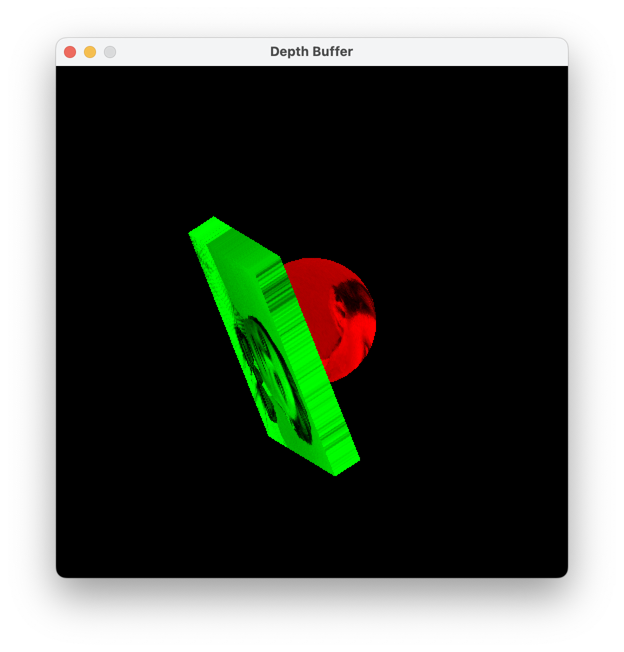
260mainDepth.c: In the appropriate places, declare, initialize, and finalize a depth buffer. On each animation frame, around the time that you clear the RGB buffer, also clear the depth buffer. Use the new meshRender. Also make various other required changes. I recommend that you inspect every line of code in this file. Test your program. The easiest way to make a strong test is to use two meshes that intersect. Here's mine:
The point of depth buffering is to get objects to occlude correctly. The point is not to improve the code's speed. However, we get a speed improvement as a bonus. To understand how, consider: What happens if a triangle crosses the boundary of the window, so that some of its pixels are outside the window? Well, pixSetRGB ignores requests to paint those pixels, so your image is unharmed. But your rasterizer still wastes time trying to paint them. For the first time in the course, you can now avoid this wasted time.
270triangle.c: In a copy of 260triangle.c, implement the optimization.
270mainDepth.c: In a copy of 260mainDepth.c, include the new version of triangle.c. Don't change anything else. Test. You should get exactly the same output as you did before. To see the effects of the optimization, try using a mesh that transgresses the window boundaries. (In my test, the optimization quintupled my frame rate. Your results may vary.)
Clean up and hand in 260shading.c, 260triangle.c, 260mesh.c, 260mainDepth.c, 270triangle.c, and 270mainDepth.c.
If you have more time, then feel free to get started on the first three subtasks in the next chunk of homework.
Today you and your partner implement the viewport transformation and both orthographic and perspective projections. Then you make some demonstrations, to solidify your understanding of what the viewport and projections mean.
In this block of work, you're mostly transcribing math into code.
280matrices4By4More.pdf: Study.
280matrix.c: In a copy of 250matrix.c, implement the following functions. The second one could be done by transposing and then multiplying, but try to make it faster than that. Mine is exactly as fast as mat331Multiply.
/* Sets its argument to the 4x4 zero matrix (which consists entirely of 0s). */
void mat44Zero(double m[4][4])

/* Multiplies the transpose of the 3x3 matrix m by the 3x1 matrix v. To
clarify, in math notation it computes M^T v. The output CANNOT safely alias the
input. */
void mat331TransposeMultiply(
        const double m[3][3], const double v[3], double mTTimesV[3])

/* Builds a 4x4 matrix for a viewport with lower left (0, 0) and upper right
(width, height). This matrix maps a projected viewing volume
[-1, 1] x [-1, 1] x [-1, 1] to screen [0, w] x [0, h] x [0, 1] (each interval
in that order). */
void mat44Viewport(double width, double height, double view[4][4])

/* Inverse to the matrix produced by mat44Viewport. */
void mat44InverseViewport(double width, double height, double view[4][4])
280camera.c: Study. This file defines a camera "class", much like the texture and mesh classes that we already have. Three of its "methods" are not yet implemented. Implement them using the data stored in the projection member.
280mesh.c: In a copy of 260mesh.c, change meshRender to have the following interface. Just before triRender, perform the viewport transformation and the homogeneous division on the XYZW part of the varyings. You may assume that the vertex shader has put XYZW into the first four entries of its output vary. You may assume that W is non-zero. (At this point in the course, W might be zero in rare cases. And then your program might malfunction. That's okay for now.)
void meshRender(
        const meshMesh *mesh, depthBuffer *buf, const double viewport[4][4],
        const shaShading *sha, const double unif[], const texTexture *tex[])
Remember that the camera is at the origin of the world and pointing down the world's negative Z-axis. From the camera's point of view, the world X-axis points right and the world Y-axis points up.
280mainViewProj.c: Start with a copy of 270mainDepth.c. Your goal is to make a new program that produces exactly the same imagery, but using the viewport and projection. So make a viewport transformation based on the window size, and pass it to meshRender. Configure a camera with an orthographic projection. In the X direction, the viewing volume should run from 0 to the window width. In the Y direction, it should run from 0 to the window height. In the Z direction, its bounds don't matter much (at this point of the course). Maybe make them run from -200 to -100? Once the camera is configured, you need to get its projection matrix into the uniforms, and perform the projection in vertex shader. Also, change the vertex shader documentation to say that X, Y, Z, W are first four entries of the vary output. In the fragment shader, the depth should be the varying Z, not its negation (because the negation happens implicitly in the projection). You might want to check every line of 280mainViewProj.c, to make sure that you haven't missed any needed changes. Test.
On paper/chalkboard/tablet/etc.: Sketch a 3D scene, as follows. Draw X-, Y-, and Z-axes for the world. Sketch the camera into the scene, with a perspective frustum attached. Sketch a couple of scene objects, such as spheres and boxes. They should be about 10 meters (or whatever your length units are) in front of the camera and contained in the perspective frustum. So what are the XYZ coordinates of their centers? How big are the objects? For example, if one object is a sphere, then what is its radius? Also, try to imagine what the objects look like, from the camera's point of view. (You might be tempted to skip this part of the assignment. Skipping it may greatly increase your work in the next step. Don't skip it!)
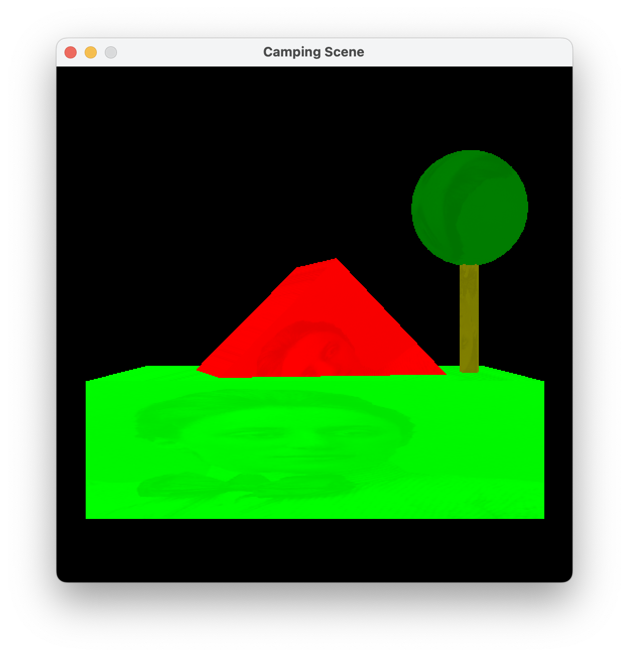
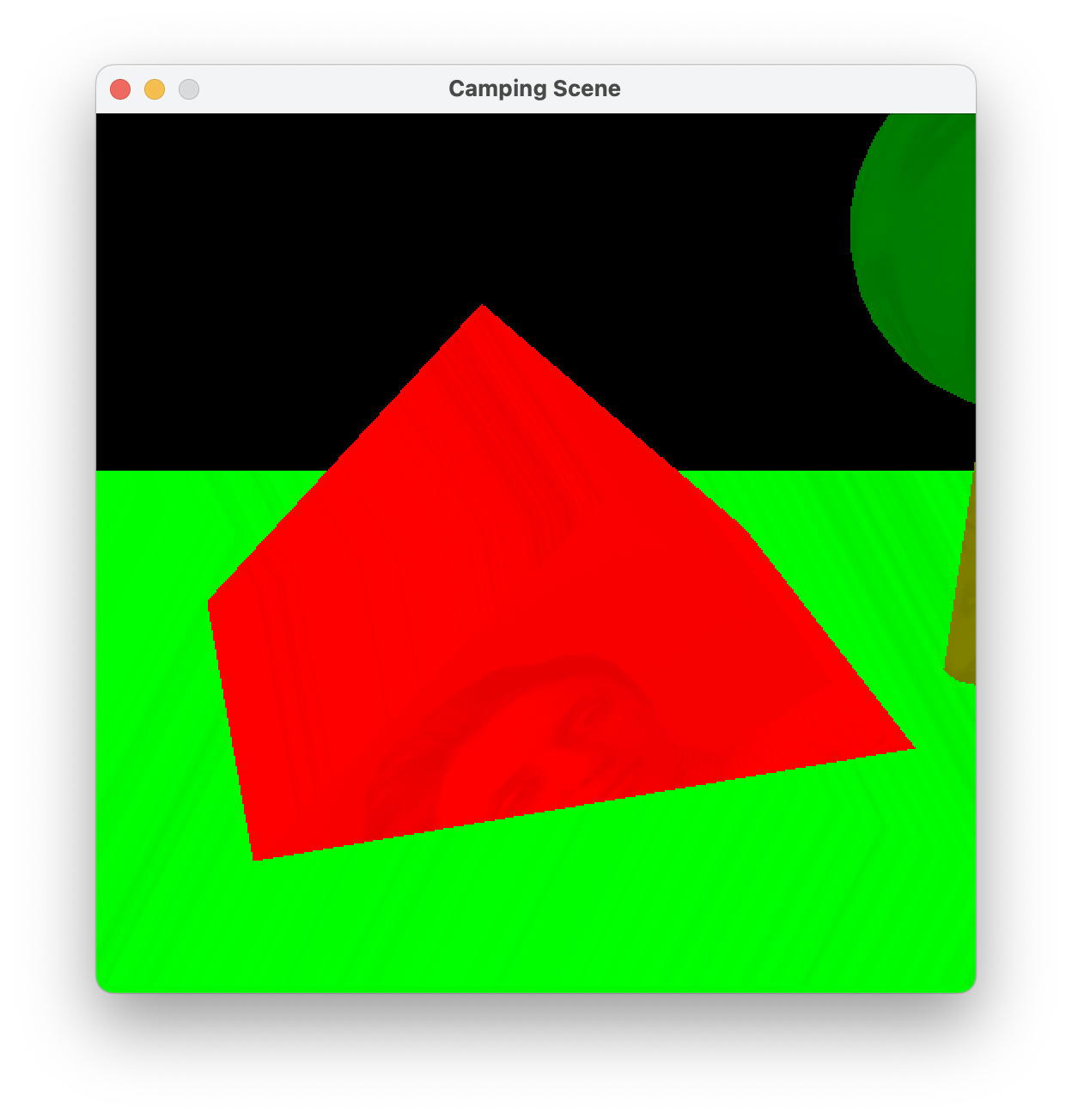
290mainWorld.c: Make this file, probably starting from a copy of 280mainViewProj.c. Implement the scene that you just sketched. Even if you're using the same shapes as in 280mainViewProj.c, you need to adjust the mesh initializations, because the mesh sizes are now in meters rather than pixels. I recommend that you build each mesh around its local origin. Use modeling transformations to place the objects where you want them. Using camSetFrustum, let the user switch back and forth between perspective and orthographic by pressing the P key. Here's mine, which shows a tent erected under a tree (in perspective):
Clean up and hand in 280matrix.c, 280camera.c, 280mesh.c, 280mainVP.c, and 290mainWorld.c.
Today you and your partner have two features to implement: a movable camera and perspective-corrected interpolation.
The camera's position and orientation are controlled by an isometry (a combination of rotation and translation). The camera's effect in the vertex shader is the inverse isometry followed by the projection.
300isometry.c: Study. As the course proceeds, isometries become increasingly important to us, so they're worth turning into a class. Implement the two un-implemented methods.
300camera.c: Study. Pay particular attention to camLookAt and camLookFrom, which are extremely useful in controlling a camera's isometry. You are expected to understand how they work. Draw pictures to figure them out. Talk to me, if you can't. There are four un-implemented methods. Implement three of them by copying your code from 280camera.c. Implement the other method too.
300mainCamera.c: Make a copy of 290mainWorld.c. Change how the camera sends a 4x4 matrix to the vertex shader. Use camLookAt to aim the camera at the scene objects. If they are clustered around the point (0, 0, -10), and you view them from a distance of 10 with φ = 0 and θ = -π / 2, then you should get the same image as you did earlier. Test.
310mainCamera.c: In a copy of 300mainWorld.c, add a keyboard handler to let the user control the camera's isometry. The left- and right-arrow keys should change θ. The up- and down-arrow keys should change φ. Let's say that the O and L keys should change the camera's distance from its target. (Changing that distance requires calls to both camLookAt and camSetFrustum. Why?) The P key should still control the projection type. Test. Here's mine:
awesome.png: Download this aptly named 8x8 image.
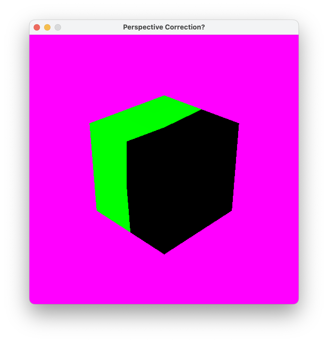
320mainInterpolating.c: Study. When you run this program, the texture should appear bent, as in the screenshot below left, because we have not yet corrected our interpolation for perspective.
330mesh.c: Make a copy of 280mesh.c. Formerly you performed the homogeneous division on just the XYZW components of the varying vector. Now you perform homogeneous division on the entire varying vector.
330mainInterpolating.c: Start with a copy of 320mainInterpolating.c. Add another varying. Coming out of the vertex shader, it always has value 1. Then the mesh renderer, that you just made, sets it to 1 / W, right? The fragment shader receives it as an interpolated 1 / W value. The fragment shader should immediately divide all varyings after XYZW by this interpolated 1 / W value, to balance the division by W that happened in the mesh renderer. Then it uses those divided varyings to produce its RGBD answer as usual. That's it. When you run the program, the bending problem should be gone, as in the screenshot below right.

Clean up and hand in 300isometry.c, 300camera.c, 300mainCamera.c, 310mainCamera.c, 330mesh.c, and 330mainInterpolating.c.
In my 310mainCamera.c, the user is able to get a close-up look at the tent only. How could I enhance the user interface, so that the user could get close-up looks at whatever they wanted — for example, the tree?
Suppose that I have perspective-corrected interpolation working, but I want to go back and make the un-corrected image seen above left. Well, I can accomplish this feat by editing just the shaders in 330mainInterpolating.c. How?
There's only one more feature for your partnership to implement: clipping. Then our triangle-rasterizing 3D graphics engine is essentially complete. Along the way, let's make some new artwork, so that we can more strenuously test how perspective works.
340landscape.c: Skim. This file helps us randomly generate grids of elevation data. Those grids can be fed to certain initializers in 250mesh3D.c to make landscape meshes.
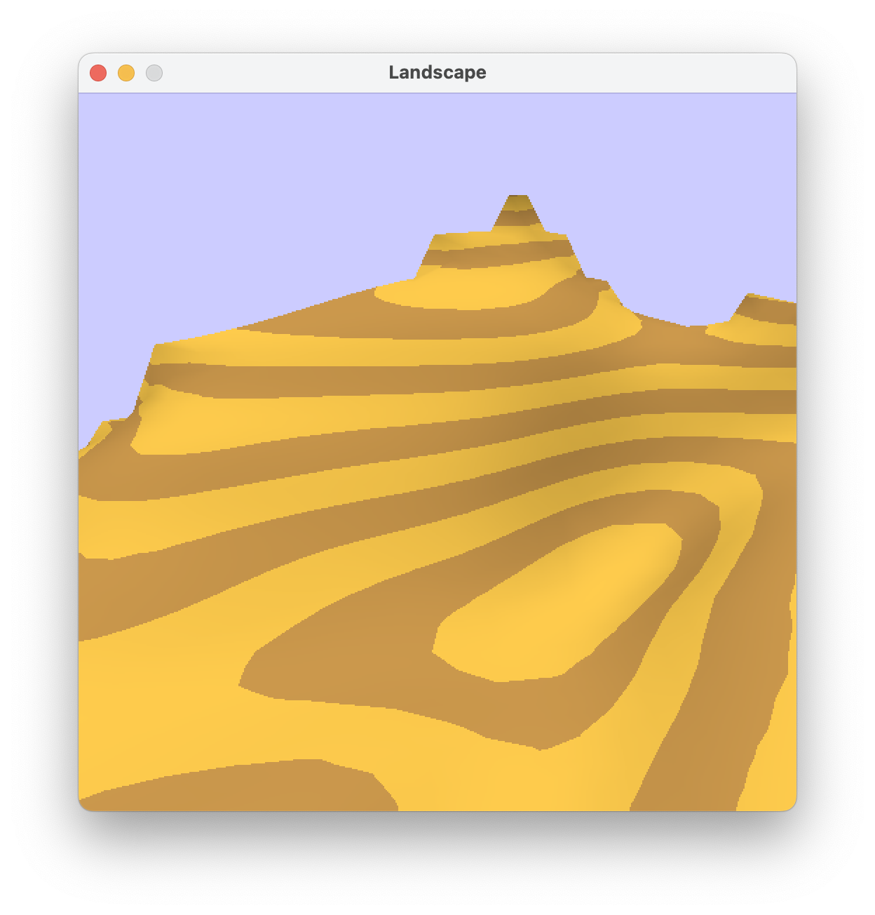
340mainLandscape.c: This program should compile and perhaps even run, but it has a major bug, in that I forgot to perspective-correct the interpolation. Oops. Edit the varyings, vertex shader, and fragment shader accordingly. Then the program should work, producing imagery like that of the first two screenshots below. Try out the keyboard controls. Intuitively, the program is a virtual helicopter ride over a desert landscape. If the rendering is unbearably slow, then decrease LANDSIZE. If you decrease LANDSIZE and the landscape looks too crazy, then try decreasing the number and/or size of the faults, blurs, and bumps, that randomly generate it.
340mainLandscape.c: I would like you to experience for yourself what the problem is, please. Fly the helicopter low over the desert, so that the camera views the landscape at a shallow angle. In this situation, switching between orthographic and perspective projections should produce a strong visual effect. The program should work perfectly when all scene objects are in front of the camera. On the other hand, undesirable artifacts (and slow frame rates, and maybe crashes) should arise when the camera is in perspective mode and objects are at or behind the camera plane. For example, the first image below is okay. I push the helicopter forward slightly to get the second image, which is still okay. I push the helicopter forward slightly again to get the third image, which is terribly wrong.


350mesh.c: Implement the near-plane clipping algorithm discussed in class. Shall I refresh your memory? The algorithm happens in normalized device coordinates — that is, after projection and before viewport or homogeneous division. A vertex a is clipped if either a3 ≤ 0 or a3 < -a2. If all three vertices in a triangle are clipped, then the entire triangle is clipped out. If two vertices are clipped, then the triangle is clipped to a smaller triangle. If one vertex is clipped, then the triangle is clipped to two smaller triangles. If no vertices are clipped, then the triangle is not clipped at all. The vertices of the smaller triangles are found by linear interpolation. More specifically, suppose that vertex a is clipped and vertex b is not. Then a + t (b - a), with t = (a2 + a3) / (a2 + a3 - b2 - b3), is where the near plane intersects the triangle side from a to b. This interpolation applies to not just the XYZW coordinates but rather the entire varying vector.
350mainClipping.c: In a copy of 340mainLandscape.c, replace 330mesh.c with 350mesh.c. That's it. Then stress-test the program. There should be no artifacts or crashes when objects cross the camera plane. Instead, objects might appear clipped where they cross the near plane. Both perspective and orthographic projections should work.
Clean up and hand in 340mainLandscape.c, 350mesh.c, and 350mainClipping.c.
Congratulations! Our first 3D graphics engine is complete. It might not seem complete, because we have made only rudimentary images with it. However, a wide variety of features, effects, and applications can be implemented using what we have now.
Let's take this opportunity to package our graphics engine for posterity. This packaging has several benefits. First, we can release a binary version without giving away the source code. Second, we can hide the implementation of the engine from its users, so that they use only the interfaces. Third, those users do not need to re-compile the graphics engine every time they compile their programs. (In a small project like this, the compilation time is small. In larger projects, the time can be huge.) Fourth, the users need to include just one header file instead of 10 or more C files.
360engine.h: Skim. This header file specifies public interfaces without committing to any details about implementation. For example, the functions in 270triangle.c are not listed, because they are not intended for public use. If you have some other functions that you want to make public, then feel free to add them. But don't remove or change any functions that are there.
360engine.c: Compile following the directions at the top of the file. The resulting 360engine.o is the binary version of the graphics engine.
360mainEngine.c: Start with a copy of 350mainClipping.c. Edit it to #include 360engine.h (and 040pixel.h) but none of our other engine files. At the top, change the compilation instructions, so that the user knows how to link to 360engine.o. Test that the program works correctly.
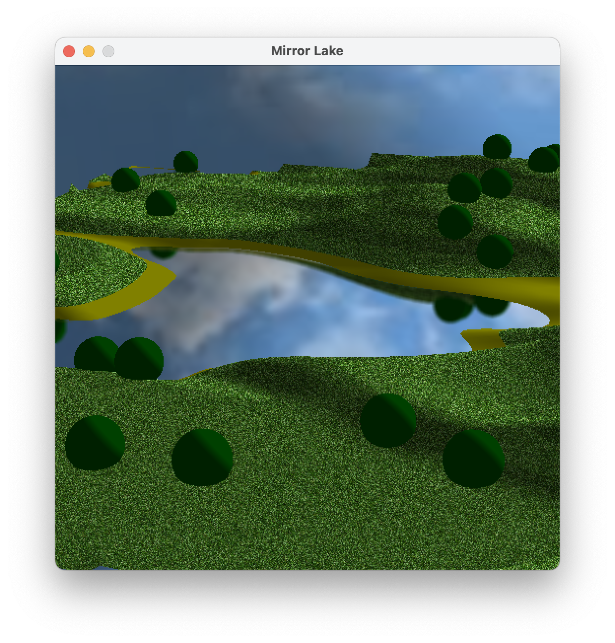
If you ever wanted to play around with this graphics engine — try a weird effect, make better art, etc. — then now would be the time. See the two examples below. On the left is the simple RGB cube that I showed you on the first day of class. On the right is a heavily modified 360mainEngine.c. I make it by first switching the artwork to a temperate grassy climate. I add a textured sky and untextured shrubbery. To the shaders I add a simple lighting effect (which we study in a couple of weeks). I add a lake, a mirror effect on the lake, and a blur effect on the mirror. All of these features are added in main.c; no edits to the engine are required.
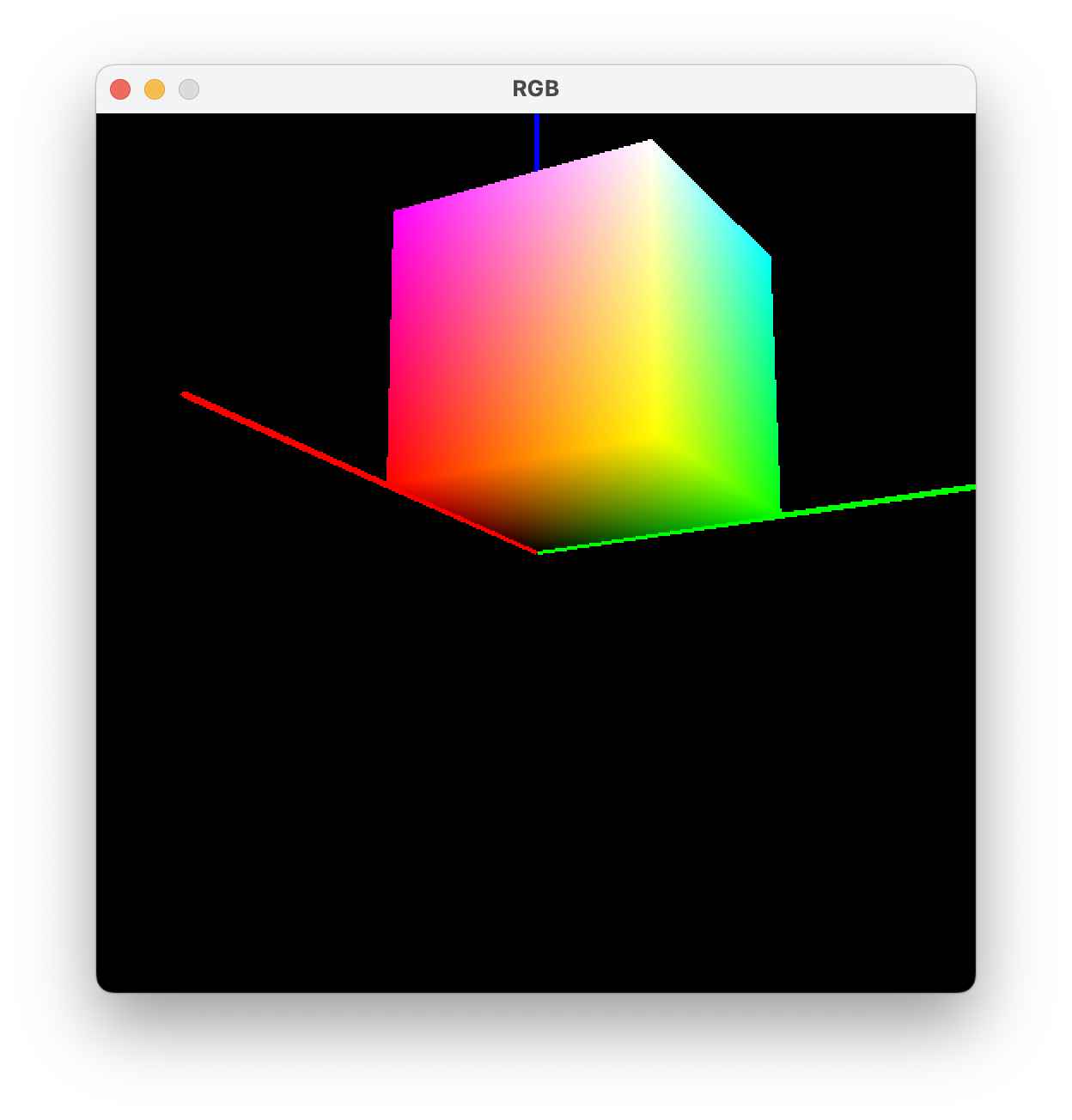
In the RGB cube application above, I use the standard box mesh from 250mesh3D.c, with vertex attributes XYZSTNOP. I use no textures. So how do I color the cube? (There are several ways to do it. You're not supposed to read my mind, but you are supposed to come up with something workable.)
In the mirror lake application above, how do I make the sky? Be careful. And here's a much harder question: How do I achieve the mirror effect? (It's not faked. It's recomputed in every frame to automatically handle any changes to the scene.)